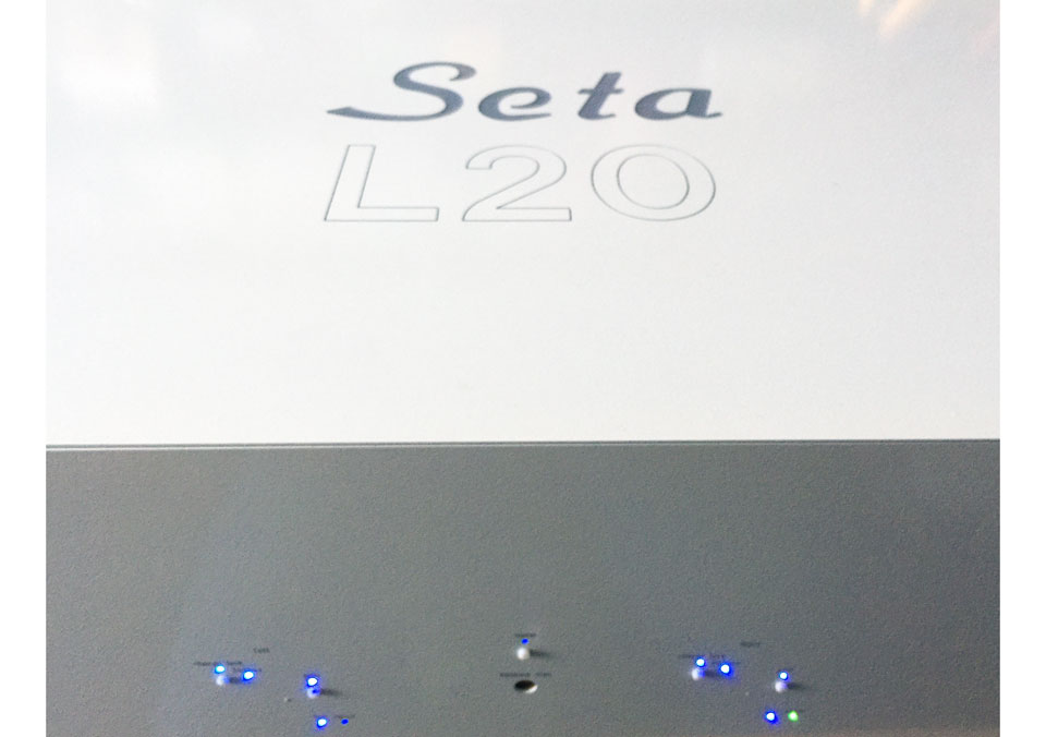
Seta® L20 mk2
Dual-Mono, Fully Balanced, Direct Coupled, Rechargeable Battery Powered, Ultra-Ultra-Wide Bandwidth, Ultra-Low Distortion, Ultra-Low Noise MC Preamplifier
New features in mk2 model:
Two separate, switchable moving coil (MC) inputs
One of the MC inputs may be configured for using a moving-magnet cartridge
New front panel buttons for selecting current or voltage mode and inputs 1 or 2
The L20 is both an evolutionary and revolutionary progression from our acclaimed Seta Model L. The L20 achieves an amazing DC to 20 megahertz (-3 dB; -0.1 dB DC to 4 megahertz) bandwidth while simultaneously having an ultra low equivalent input noise (EIN) of -134 dBu. This would be a gargantuan accomplishment even for a line stage preamplifier, except that this is a phono preamplifier with its substantially higher gain requirements - and is an accomplishment because of the unavoidable and underlying physics of engineering trade offs between gain, bandwidth and noise.
Extreme measures (some would say overkill) were necessary to improve upon the already world-class performance of our Seta L - the challenge faced while developing the L20. The L20 started as an exercise to determine just what it would take to design a phono preamplifier that could better the Seta L. The Seta L already set a very high bar - it was and still remains that good! This required years of effort exploring and developing new engineering avenues, as described below.
Ultra-Ultra-Wide Bandwidth and Ultra-Low Noise: joined together in the service of the ultimate sound quality
In short, ultra-ultra wide frequency bandwidth delivers the ultimate in sound staging and definition, especially when paired with the best moving-coil cartridges. Additionally, the outstanding signal to noise ratio of the L20 provides the blackest of black backgrounds for "hearing" and enjoying the silence between the musical notes.
This feat was accomplished by connecting 32 (16 per channel) of the proven, ultra wide bandwidth front end preamplifier modules from our $4998 Seta L in parallel (a detail not revealed in our news release for the L20).
Why design a phono preamplifier in such a way?
The reason is because correlated signals (the signal from the cartridge amplified via the 16 separate preamplifier modules) sum linearly; in contrast, random, uncorrelated noise (the intrinsic noise produced by each module) sums geometrically. So, while summing 16 preamplifier modules gives 16 times the signal, the resulting noise is only 4 times - not 16 times - greater, a difference of a factor of 4 (16 divided by 4). This results in both a theoretical and measured improvement of 12 dB in signal to noise ratio compared to the already very quiet single-module Seta L - tested by incrementally adding parallel modules to the system and measuring the noise level at each iteration.
In the process, we were also able to increase the signal bandwidth by a factor of 4 over that of the unprecedented (and still unmatched, since its introduction in 2007) 5 MHz bandwidth of the Seta L. Further, via additional optimizations in the design, the overall signal to noise ratio of the L20 ends up an amazing 16 dB better than our previous flagship Seta Model L. Indeed, the resulting equivalent input noise of the L20 is actually lower than the thermal (electronic) background noise generated by the phono cartridge itself!
Engineering the L20 wasn't a simple matter of just designing a "16 times bigger jumbo circuit board" to accommodate the 16 parallel Seta L modules per channel. Several obstacles needed to be overcome for the L20 design to be successfully realized. New techniques for power management and power-up sequencing needed development, as the inrush current demanded by 16 preamplifier modules during a cold power-up was considerable, and actually comparable to that of some power amplifiers! The power supplies also were beefed up to supply the increased average current demand needed after power up.
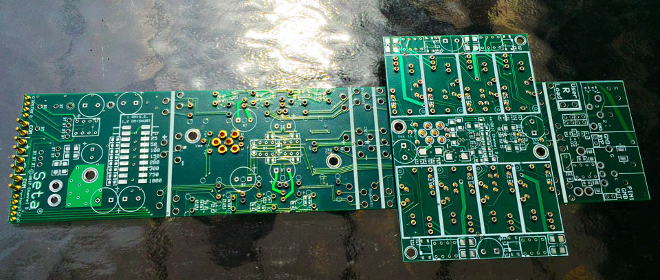
The audio circuit boards are four-layer circuit boards employing continuous internal ground and power planes for lowest noise (same as used in all of our phono preamplifiers), also an essential requirement for megahertz bandwidth circuitry, lest one end up with a megahertz oscillator instead of a megahertz preamplifier.
From there, we have taken a unique design approach. Rather than using a single large circuit board, circuit boards representing functional blocks are combined using high reliability (and very expensive) gold-finger-contact precision-machined inter-board connectors. Installing these connectors on the circuit boards is done by hand, a laborious and time-consuming process requiring several thousand assembly steps per L20 preamplifier.
Despite the effort required, the modular design permitted testing and refining the individual functional circuit blocks before committing to the final design. This is exactly the same methodology used when designing computer software, in which individual, highly debugged and optimized subroutines are connected together to produce the whole end product. It's perhaps unsurprising that, given our experience designing computer audio software products, that the same techniques would also cross over into our hardware design philosophy. The advantage, of course, is that the resulting product has in effect undergone more thorough testing and debugging than if all circuitry were combined onto a single circuit board; instead, when committing to the final design there is more assurance that the product will perform as intended.
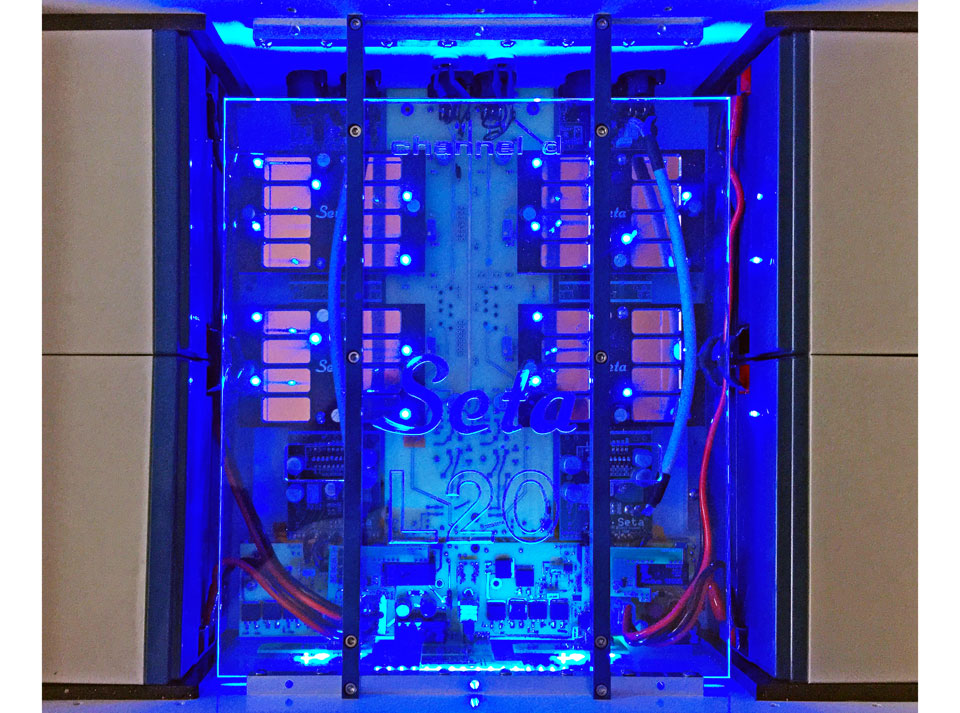
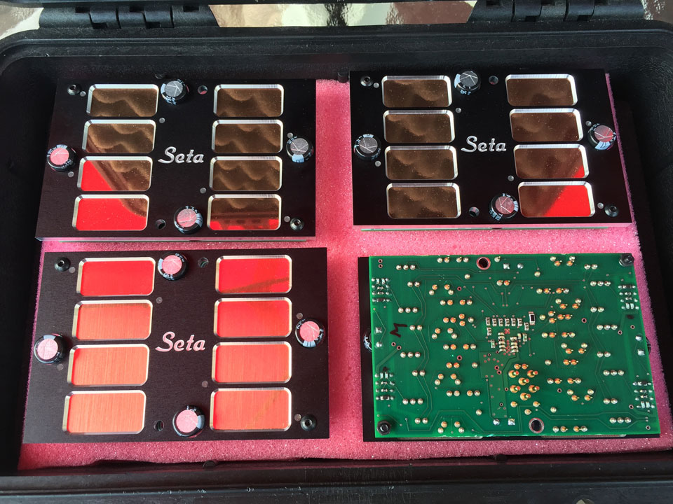
Accordingly, 32 (16 per channel) four-layer Model L input module circuit boards, after being individually tested, are installed onto four 4-layer "carrier" boards which group 8 modules together per carrier board. Again, the modular approach allows quality control assurance at each step of the way, instead of waiting to test an all-encompassing, large circuit board assembly as a final step. The four 4-layer carrier boards are then in turn mounted onto 4-layer summing boards, which each are tested again before assembling onto the 4-layer input signal routing board, which is then finally incorporated with the power supply, signal monitoring and power management board. The overall design effectively becomes a 16-layer circuit board - the total number of layers in the stack.
The L20 is a fully dual mono design with two galvanically isolated channels that only are co-located within the same enclosing chassis.
An additional benefit of the L20's outstanding bandwidth is immunity to distortions which can be produced by out-of-band, fast risetime signals such as LP impulse noise, as well as radio frequency interference - a claim which may come as a surprise to some. Input protection circuitry only comprises the first step in effective out of band noise rejection. To deliver superior performance, the amplifier must be able to respond, linearly and without distortion, to any residual out of band signals appearing at its inputs. If not, intermodulation caused by out of band signals nonlinearly interacting with the amplifier causes an easily identifiable sound characteristic, which can range all the way from a subtle veiling to an annoying harshness.
Like our other Seta preamplifiers, the power supply uses rechargeable AGM batteries with automatic management of charging, based on the presence of an input signal. The charging circuitry is completely and automatically disconnected during use, and so the preamplifier is completely floating electrically.
AGM batteries represent the best possible choice for audio, due to their extremely low impedance, coupled with simpler charging and power management circuitry compared to lithium batteries. AGM batteries also exhibit benign failure modes compared to the well-known, sometimes catastrophic failures seen with lithium batteries. And when the time comes for replacement (typically 5 years, often longer) AGM batteries are easily sourced from third parties (such as Amazon), because the types used in our Seta preamplifiers are also commonly employed in photovoltaic (solar cell) energy storage systems. Another benefit of the AGM battery is cost - about 1/5 that of a lithium battery of equivalent capacity. (The advantage of lithium over AGM is, of course, weight and size, which are not important considerations in audio electronic applications.)
Finally, the batteries are sited inside the chassis, rather than employing the practice of placing them in a separate chassis and connecting them via an umbilical. The full benefits of the extremely low electrical impedance of rechargeable batteries can only be realized by keeping the batteries very close to the circuitry. This also eliminates a potential source of electromagnetic interference from an umbilical acting as an unwanted antenna. A secondary benefit of this design is that the proximity of the batteries serves to enhance the shielding of the preamplifier circuitry, because the highly conductive plates inside the batteries double as a form of dense metallic shielding.
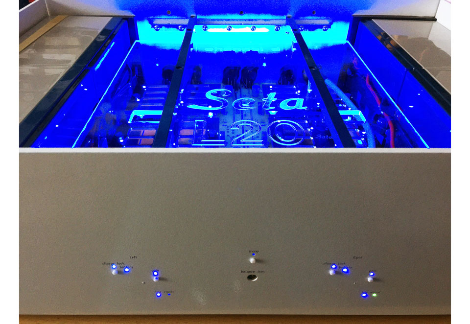
The interior of the L20 features a protective transparent Lexan cover that protects the circuitry while providing an appealing display showing the power up status of the individual modules. The L20 can be operated in this manner, or else with the powder coated 10 mm thick milled aluminum cover fastened on top.
Please see our Seta product page for specifications and a comparison with our other phono preamplifiers.
Seta L20 mk2 MSRP $73,000.00 / Factory direct price $47,000.00
Contact Channel D for ordering information.
Our manufacturing allocation for 2023 is now sold out.
Seta L20 (original model) News Release from April 2017
Several years in development, the L20 represents a cost-no-object statement product that builds on the strengths of our award winning Seta Model L MC phono preamplifier by increasing the frequency bandwidth to 20 megahertz (20,000,000 Hz) – 1000 times the bandwidth of audible frequencies - while simultaneously and dramatically increasing the signal to noise ratio and reducing harmonic and intermodulation distortion to nearly unmeasurable levels.
The Seta L20’s lower noise and ultra-low harmonic and intermodulation distortion and ultra wide signal bandwidth pay clear and discernible dividends by delivering breathtaking clarity, depth and accuracy from LPs.
The L20 is a ground breaking phono preamplifier in significant ways.
A dual-mono, direct coupled, fully balanced design, each channel has its own independent rechargeable battery power supply. Though the left and right channels share the chassis, they are galvanically isolated from each other and from the outside world. Chassis common is floating but can be tied to either or both channels.
The equivalent input noise of the L20, measured with a 1 ohm source resistance, is an astonishingly low -134 dBu, despite the extreme signal bandwidth capability.
The L20’s 24 volt power supply rails are able to swing more than 20 volts peak to peak into a 600 ohm load from DC to 100 kilohertz with negligible distortion. The L20 includes selectable voltage and current amplification modes as well as front panel adjustable gain and Mono summing mode, plus the Seta’s unique cartridge balance trim control, accessible via the front panel.
The L20 includes a 576 watt-hour internal rechargeable battery power supply. Battery recharging is automatically managed via proprietary analog Channel D circuitry (no microprocessors are used), the same as used in the Model L and all other Channel D Seta preamplifiers.
Channel D Seta phono preamplifiers - General Information
Seta phono preamplifiers offer a fully balanced (from input to output), low-noise direct coupled (DC) differential circuit design providing the users of Pure Vinyl™software with the end-to-end route to the superb performance of "flat" vinyl reproduction (linear amplification followed by software RIAA correction).
- "Flat" outputs perfect for use with Pure Vinyl software RIAA correction
- Ultra-Ultra wide bandwidth (20 MHz / 20,000 kHz / 20,000,000 Hz) delivers stunning improvements in smoothness, clarity, definition and 3-D imaging
- Precision RIAA Correction provides simultaneous "Flat" and conventional RIAA Corrected, independently buffered and balanced (XLR) and single ended (RCA) outputs
- Designed and manufactured in USA
About Seta Listening evaluations using a variety of reference systems and program material show that an important key to accurate reproduction of vinyl audio involves greatly increasing the signal bandwidth of the preamplifier front end (the first stage of amplification touching the signal from the phono cartridge).
Why? First of all, high quality phono cartridges are capable of reproducing signals well over two octaves above the audio frequency range.
While such signals are inaudible, the preamplifier also must work to amplify these signals, which are boosted over 20 dB above midrange levels (because of the standard vinyl treble pre-emphasis curve used in the mastering process). A preamplifier unable to handle out of band signals will distort in the ultrasonic region. This distortion will carry over into the audio range, affecting the reproduction of the midrange and treble.
Futhermore, the audibility of one of the most maligned deficiencies of vinyl, "pops and clicks," is a function of and can be exacerbated by the design of the preamplifier. The reason is that the transient signals caused by the stylus striking a scratch or foreign object in the groove have, in addition to large amplitude, a very fast risetime, and are unlike any musical signal. The fast risetime can cause slewing distortion in traditional narrow bandwidth or inexpensive phono preamplifiers, magnifying the audibility of pops and clicks. This nonlinear coloration from a less capable preamplifier is at least partially responsible for causing many music lovers to shun recordings in the vinyl medium! The Seta wide bandwidth design employs a fast-responding front end gain stage with a slew rate of over 500 volts per microsecond (Model L), making it immune to transient distortions induced by pops and clicks, minimizing their impact on the listening experience. (The slew rate of the Seta output is deliberately limited to avoid causing slew rate distortion in any following components.)
How much bandwidth is enough? The rule of thumb for linear signal reproduction is ten times (an order of magnitude) greater than the signal of interest. With that criterion, the amplifier is able to linearly reproduce out of band signals, while preserving the integrity of the midrange and treble without the "haze" caused by, and characteristic of, ultrasonic intermodulation distortion. Going still further, extending the bandwidth by two orders of magnitude delivers a stunning improvement in three-dimensionality and imaging. This principle is continued by the Seta L20, which has a signal bandwidth three orders of magnitude (1000 times) that of audible frequencies.
Why don't more phono stages have ultra wide (megahertz) bandwidth? Why do some line stage preamplifiers have megahertz bandwidth? It's one thing to design a line stage preamplifier, and quite another to design a phono stage. The difference is the extreme amount of gain required in a phono stage - around 100 times (40 dB) greater than a typical line stage. A trade off exists between gain, signal bandwidth, noise and distortion. In most phono stages, the required high gain means that the other design parameters must be engineered more conservatively. This was the case until the introduction of our 5 megahertz bandwidth Seta Model L in 2007. The lower gain required for a line stage makes it easier to design with wide bandwidth. For instance, our special-purpose Buffer Amplifier products, introduced in 2012, are essentially simplified line stages - and have a 20 megahertz bandwidth - without resorting to the new (and much more expensive to implement) design methodologies employed in our 20 megahertz bandwidth Seta L20.
Surface Mount vs. Through-Hole Components To dispel misinformation which we've seen on the Internet and in print advertising: surface mount components provide the shortest signal paths and highly optimized circuit layouts, with low stray inductance, low stray capacitance, low temperature coefficients, high stability, improved unit to unit consistency and consequently better performance than old-fashioned through-hole circuit components. Surface mount manufacturing is not strictly the outcome of short-sighted "value engineering" - it is the result of the never-ending quest for increased performance of electronic components and circuits; lower manufacturing costs are a welcome side effect. There are cheap surface mount components just as there are cheap through-hole components, both of which deliver inferior performance. However, the performance of all through-hole parts are handily eclipsed by the best surface mount components, as used in our preamplifiers. Further, certain types of high-performance circuits simply cannot be created with through-hole components, especially those requiring ultra wide bandwidth, which demands short signal paths and surface mount components.
There is one specific exception where through-hole parts deliver better performance: high performance film capacitors. The solid organic polymer dielectric used in all high performance film capacitors cannot withstand the high temperatures encountered during surface mount manufacturing. In response, alternative high-temperature-compatible organic polymer dielectrics have been introduced, such as polyphenylene sulfide (PPS). We have evaluated these parts and have found them markedly inferior to other film capacitors, such as the metallized polypropylene type that we use for RIAA and filtering circuits. PPS has poor thermal stability, making it impossible to hand select PPS components for precision tuned circuits, because the values of PPS capacitors change too much when exposed to the heat from soldering. They also have inferior dielectric absorption (causing a loss of definition and veiling) and DC leakage compared to metallized polypropylene - with DC leakage (and other parameters) changing substantially depending on the atmospheric humidity! They are also not available in higher values, leading to less than optimal circuit designs (even if they otherwise matched the performance of other polymer film capacitors). Accordlngly, among surface mount components, surface mount film capacitors (and only surface-mount film capacitors) are ill-suited to high performance audio.
Of course, as any electrical engineer who has worked with practical circuits knows, high performance through-hole film capacitors (partly because of being large-sized, through-hole type parts, but also because the permittivity of the dielectric material used decreases with frequency) cannot be used for critical (and essential) high frequency power supply bypassing - they become inductive at relatively low (several hundred kHz) frequencies. This is where MLCCs (multilayer inorganic dielectric capacitors - we'll use the "dirty word" here - ceramic; but rest assured that today's 21st century ceramic capacitors use exotic materials such as zirconium tin titanate / C0G and barium titanate / X7R that are definitely not "your father's ceramic capacitor") really shine, because of having exceptionally low inductance (and ESR, equivalent series resistance). This is a direct consequence of their miniaturized size, internally having hundreds of layers of electrodes separated by dielectric - an amazing feat of manufacturing achieved only in the last several years. On the other hand, inorganic dielectrics are definitely unsuitable for use directly within the audio signal path because of dielectric absorption, higher dissipation and their generally wider capacitance tolerance (tight tolerance is needed for precision filter circuits such as rumble filters or RIAA EQ), plus susceptibility to microphony (because the X7R dielectric used in the lowest inductance parts exhibits piezoelectric activity). However, these drawbacks are unimportant considerations for power supply bypassing, where low ESR, low inductance and small size are of paramount importance.
| Feature |
Benefit |
| Ultra-wide linear
signal bandwidth (-3 dB at 20 MHz, Seta L20; -3 dB at 5 MHz, Model L; -3 dB at 1 MHz, Piccola); Direct Coupled circuitry. No
Capacitors in signal path |
Improved Smoothness,
Clarity, Definition and 3-Dimensional Imaging |
| Fully Balanced, Complementary
Circuitry |
Reduced Noise and
Distortion |
| Minimum Signal Path
Design |
Preserves Signal Integrity |
| Low Impedance AGM
Internal Rechargeable Battery |
50 Ampere, Deep
Power Reserve Preserves Signal Dynamics |
| FET or Bipolar Hybrid
Circuit Topology (Model H or Model L) |
Performance Tailored
to MM or MC Cartridges |
| Video Bandwidth, Balanced
Low Impedance Output Amplifier |
High Noise Immunity; Not Affected by Connected
Equipment or Length of Output Interconnect |
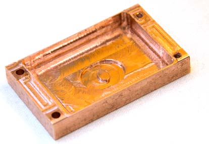 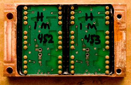
Seta Model L / H preamplifier's hybrid, video - bandwidth amplifier modules are electronically and acoustically isolated and kept at a stable operating temperature and environment (constant humidity) by enclosing and sealing them in a block machined from a solid piece of oxygen-free high conductivity copper. Each module is carefully tested and characterized before and after being hermetically sealed in the copper block.
Noise Seta preamplifiers, besides (or should we say, despite?) providing the widest bandwidth of any phono preamplifiers available, also feature low noise that ranks among or better than the world's finest phono stages. Here is a comparison of measurements performed by Stereophile (including issue dates for verification) of the signal to noise ratio (SNR) of moving coil phono preamplifiers, including our Seta Model L. Higher numbers are better. The quietest are highlighted in boldface.
| Phono Preamplifier (MC Input) |
Unweighted SNR |
A - Weighted SNR |
From SP Issue: |
Accolades |
| Channel D Seta Model L20 mk2 |
81 dB |
87 dB |
|
|
| Channel D Seta Model L |
59 dB* |
67 dB* |
August 2010 |
Stereophile Class A Recommended Component |
| Boulder 1008 |
60 dB |
64.75 dB |
July 2010 |
Stereophile Class A Recommended Component |
| Vitus Audio MP-P201 Masterpiece |
53.6 dB |
62.8 dB |
September 2010 |
Stereophile Class A+ Recommended Component |
| Nagra VPS |
not reported |
61 dB |
September 2008 |
Stereophile Class A Recommended Component |
| Boulder 2008 |
not reported |
49 dB |
July 2002 |
Stereophile Class A+ Recommended Component |
*The signal to noise ratio has been improved in the year 2015 and later production for the Model L by approximately 4 dB from the numbers shown above obtained from the August 2010 Stereophile review, and are reflected in our current published specifications, e.g., 71 dB A-Weighted SNR for the Seta Model L.
Measurements of distortion levels, bandwidth and RIAA accuracy are best gleaned from reading the associated reviews, but the Seta Model L ranks near the top, if not at the top of the list in this regard. For further confirmation, see John Atkinson's follow up review of the Model L (December 2013 Stereophile, download here) with additional highly favorable distortion and RIAA accuracy measurements. Note: In that report, John also made another measurement of the signal to noise ratio, but unfortunately had the Seta configured for single ended rather than balanced mode, resulting in a substantially diminished SNR!
Circuit Design The Seta front end circuitry is tailored to preserve the strengths of the characteristics of different cartridge types. A low noise, high impedance FET front-end is used in the Seta Model H for moving-magnet and other high output cartridges, while an ultra-fast, ultra low noise bipolar transistor front end is used in the Seta Model L for low impedance, low output moving coil cartridges.
The circuit topology is fully differential, balanced direct-coupled circuitry from input to output. The front-end active circuitry is surrounded on five sides by a sub-enclosure machined from a solid block of copper. This provides electronic and acoustical noise isolation plus thermal stabilization. Bare copper metal surfaces are coated with a clear lacquer to prevent oxidation (and to maintain their beautiful color).
Unlike many other preamplifier designs: the rated (-3 dB) bandwidth is independent of gain.
The Seta Piccola phono stage uses carefully selected, ultra low distortion, low noise ICs also in a fully balanced configuration with a bandwidth of 1 MHz (-3 dB).
All Seta products use 0.1 percent tolerance precision low noise metal film resistors in all critical areas.
Rechargeable Battery Power Supply The low-impedance, internally located AGM rechargeable battery is capable of supplying 50 amperes of current, outperforming other types of batteries used in audio applications. The battery is conditioned and kept float-charged by a proprietary, uniquely designed rail balancing circuit, rather than use an "off the shelf" microprocessor based conditioning and monitoring circuit, which would introduce unwanted noise. Locating the battery inside the preamplifier chassis also insures that the battery is in the same electrical environment as the sensitive front-end circuitry, eliminating potential sources of noise pickup. The external charging supply is automatically disconnected when an input signal is detected.
Mechanical All connectors are the best available, professional quality Neutrik gold contact XLR and WBT gold contact helical conductor wide bandwidth RCA (Model L / H).
Pushbutton actuated, sealed gold contact small signal relays are used to change gain settings (four different gain settings, Seta Model L / H). A unique rear-panel rotary balance trim control with a precision 2 dB range provides for fine cartridge channel balancing (the trim setting is not affected by the overall gain).
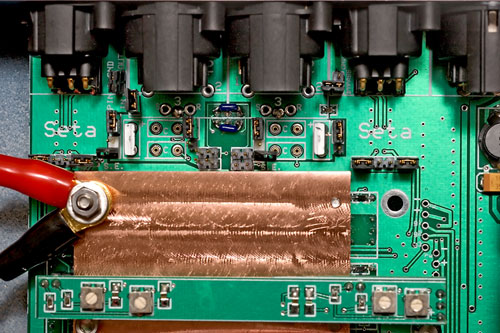 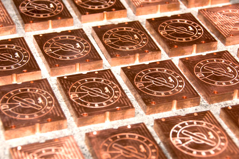
Interior Close-up View of Seta, showing Solid Copper Front-End Circuitry Isolation Block (Left);
New Seta Model L / Model H Preamplifier Modules (Right)
Measurements Of course, the "last word" in the evaluation of audio products should be done by using the best "measurement:" real-world, listening-based evaluation. However, we believe that careful measurements also are essential, if only to insure that the product you receive actually conforms to the designer's original vision and intent.
Seta preamplifiers incorporate many unique or unusual design features contributing to their high performance
- Ultra low impedance AGM rechargeable batteries used as charge storage reservoir and power supply filter; proprietary, exclusive charging and maintenance circuitry specially designed by Channel D and proven, refined and used exclusively in our phono stage designs for over 5 years
- State of the art, premium quality low - ESR polymer dielectric electrolytic and tantalum filter capacitors
- Ultra precision (0.1% tolerance) metal film low noise 1206 / MELF surface mount resistors used throughout
- Ultra low distortion, low impedance differential output stage with greater than 40 MHz signal bandwidth
- RIAA Compensation Network with precision, hand matched components
- True single ended outputs obtained by differential summing and balanced signal input for lowest possible noise (high common mode rejection) on single ended connections
- All Channel D Seta preamplifier products feature a signal bandwidth of DC to 1 MHz (-3 dB) or greater
In keeping with our continuing efforts to enhance and improve our products, we reserve the right to change specifications and pricing without notice.
|
